
Aerial Networks
Dome and inline closures with UV-stable shells and strong pole or messenger mounting.
- UV resistance and shell material
- Pole or strand mounting
- Wind and ice loading
Route type, cable count, splice capacity, sealing class, tray stack and mounting change what a suitable closure looks like.
Use each profile as a starting point, then validate the actual route, cable entry, sealing requirement and mechanical protection.
Dome and inline closures with UV-stable shells and strong pole or messenger mounting.
High-capacity joint closures with IP68 sealing and enough tray stack for later branching.
Compact splice boxes and terminal boxes for ODN splitting points and subscriber entries.
Rack-mount splice trays and small closures for high-count backbone and MPO trunks.
Non-metallic closures along OPGW and substation routes where isolation matters.
Exposed links that demand sealed closure bodies, gaskets and UV-resistant housings.
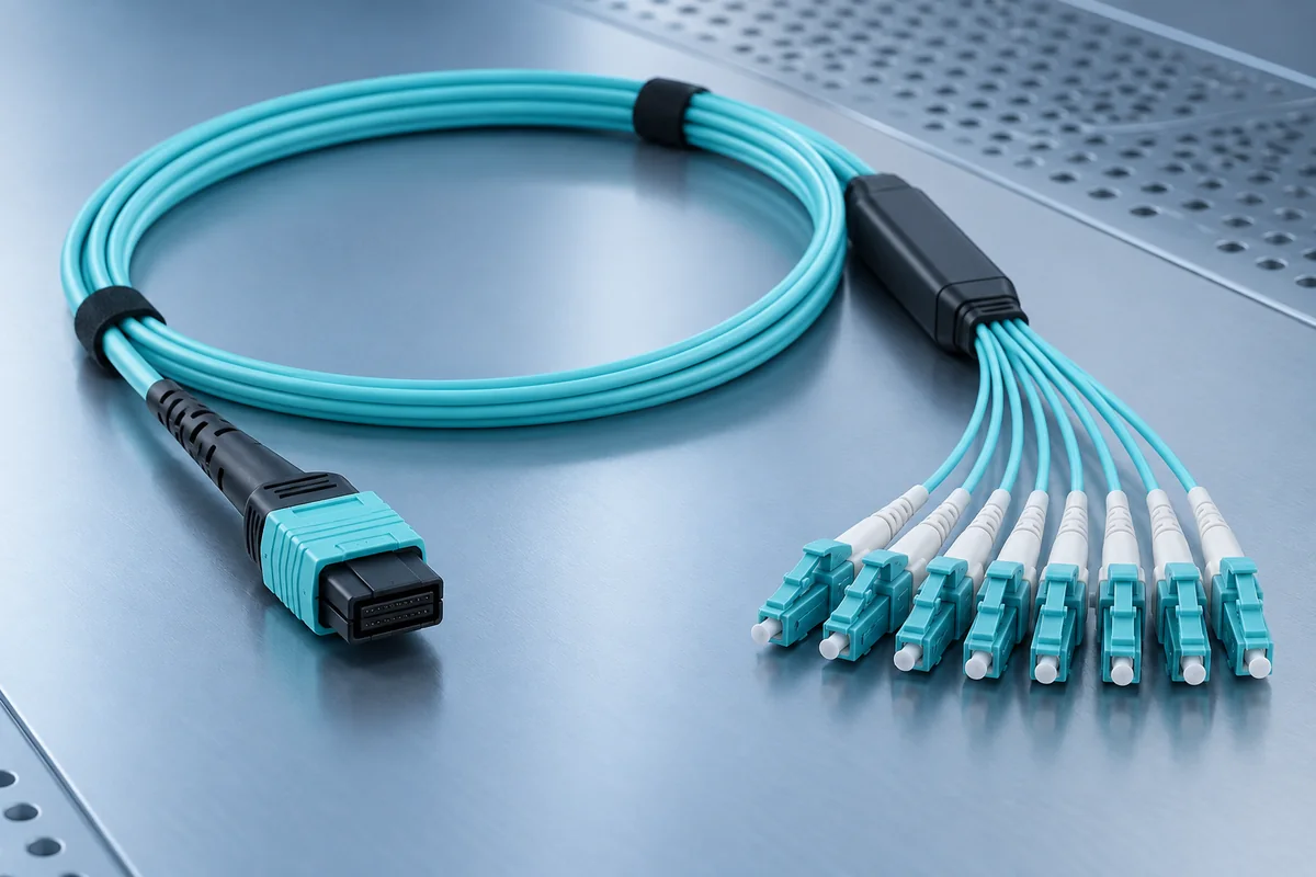
High-capacity closures can save space, but tray layout, bend radius, cable entry sealing and re-entry access become more important. Outdoor networks may use fewer splice counts yet demand better sealing, gasketing and route protection.
A useful closure specification answers these questions even when the environment changes.
Record cable count, fiber count, splice capacity and spare capacity for later branching.
Confirm pole, strand, wall, rack or buried mounting and the required bracket.
Define IP rating, immersion time, gasket material and cable entry sealing method.
Define inspection, continuity, splice loss and OTDR requirements before commissioning.
Cable count, splice capacity, mounting type, environment and sealing class are the most useful first details.